Installation guides, API reference, downloads, and support for all SGS products.
Find everything you need to install, configure, and support SGS fault indicators and communication systems. This hub is designed to help utilities, field crews, and engineers quickly access the information required to keep systems running efficiently.
If you cannot find the information you need, contact the SGS support team for technical assistance, product guidance, or deployment support.
Doc #42025090HN
Position the reset tool over the fault indicator's dome, aligning the magnet with the label opposite the battery caps. Hold it for about 1 second. Remove the tool once the LEDs begin a test flash sequence; they will stop flashing when the test is complete.
Initiating a Manual Test starts a cellular check-in and GPS lock. The LEDs will flash up to 10 minutes as the fault indicator connects and transmits data. Wait until the LEDs stop or check-in is confirmed at www.portal-sgs.com before starting another test.
While the LEDs are flashing, place the reset tool's magnet over the label on the side of the fault indicator opposite the battery caps. Hold it there for about 1 second; the LEDs will then stop flashing.
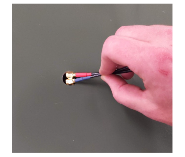
The FI-5A-W requires one 3.6V AA battery and one 3.6V C battery, each with a wired connector. Purchase replacement batteries from SGS or an authorized distributor. For replacement, always change both batteries.
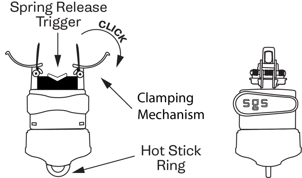
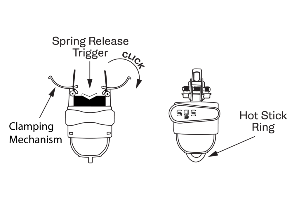
Pull open the Clamping Mechanism with your thumbs until it locks into place. Once cocked, the unit will remain locked in the "open" position.
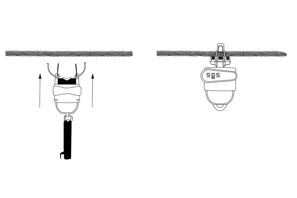
Attach the device to a shotgun stick.
Position the conductor between the open Clamping Mechanism and forcefully push the device upward onto the line. Once the Spring Release Trigger receives enough pressure, it will release the spring, clamping the conductor and securing the device in place.
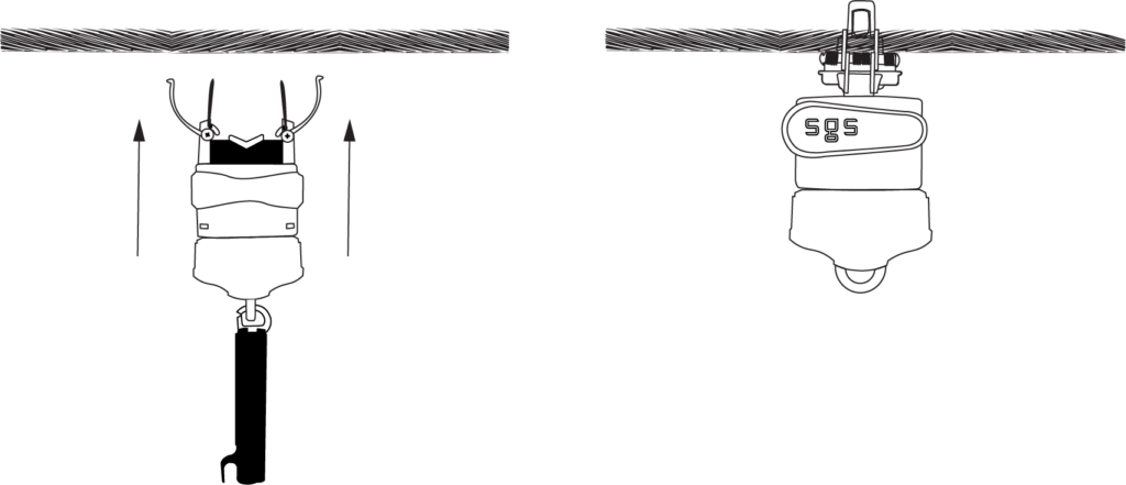
Ensure the Clamping Mechanism arms are touching for an accurate reading. Open the shotgun stick and detach it from the device.
Doc #v325250HN
Place reset tool over fault indicator's dome so reset tool's magnet is over the label on the side opposite from battery caps. Hold magnet in place for approximately 1 second. The LEDs will begin to flash through a test sequence and will stop flashing once the test sequence is complete.
While LEDs are flashing, place reset tool over fault indicator's dome so reset tool's magnet is over the label on the side opposite from battery caps. Hold magnet in place for approximately 1 second. The LEDs will stop flashing.
The FI-5A requires one 3.6V AA battery and one 3.6V C battery, each with a wired connector. Purchase replacement batteries from SGS or an authorized distributor. For replacement, always change both batteries.
Pull open the Clamping Mechanism using thumbs until it locks into place. Once the Clamping Mechanism has been cocked, the unit will lock in the "open" position.
Attach the device to a shotgun stick.
Position the conductor between the open Clamping Mechanism, and with a forceful upward movement, install the device to the line. When the Spring Release Trigger receives sufficient pressure, the spring will release, clamping the conductor and setting the device into place.
Clamping Mechanism arms should be touching each other to assure accurate reading. Open the shotgun stick and remove it from the device.
Doc #0409_2026HN
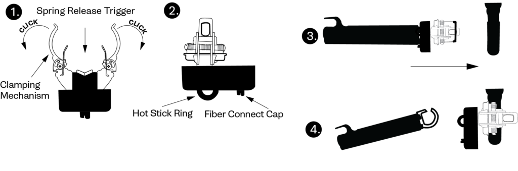
Use thumbs to pull open Clamping Mechanism. Once Clamping Mechanism is pulled sufficiently apart, the arms will lock into place.
Attach the fault indicator to a hot stick.
Position cable between open Clamping Mechanism. With a forceful push forward, install device on cable.
Clamping Mechanism arms should be touching each other to assure accurate reading. Remove hot stick from device.
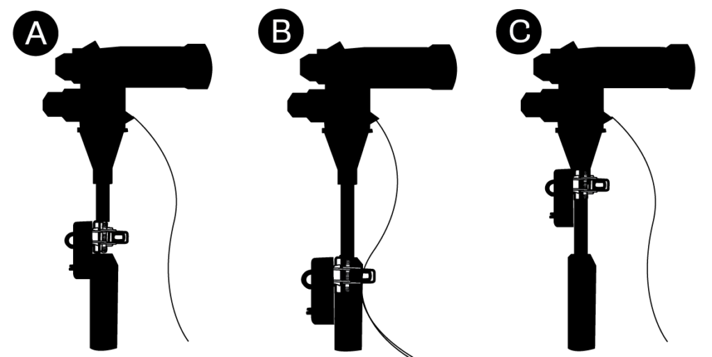
For Methods A and C, ensure no contact with concentric neutral or bleed wire.
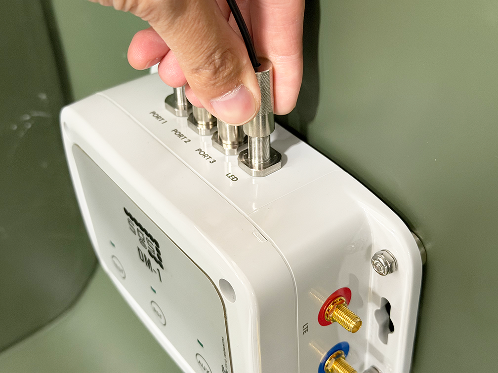
Install the FCI so the face of the unit aligns with the adjacent conductor. The back surface of the FCI and the adjacent conductor should be on the same flat plane. Mounting the device as far as practically possible from adjacent conductors minimizes the risk of signal interference.

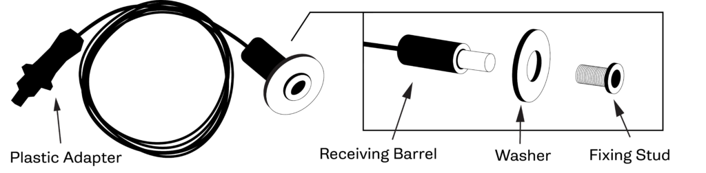
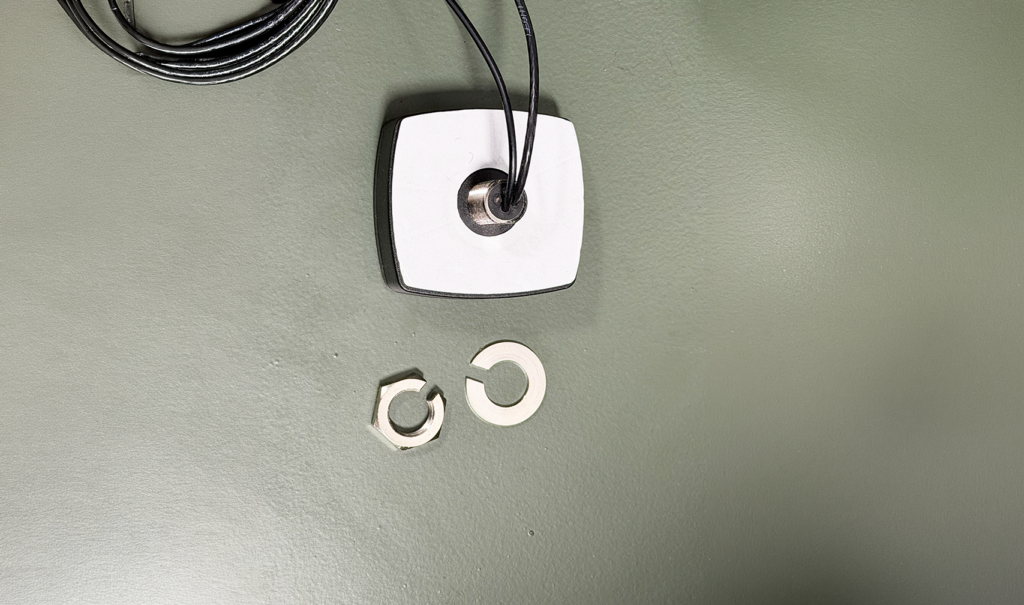
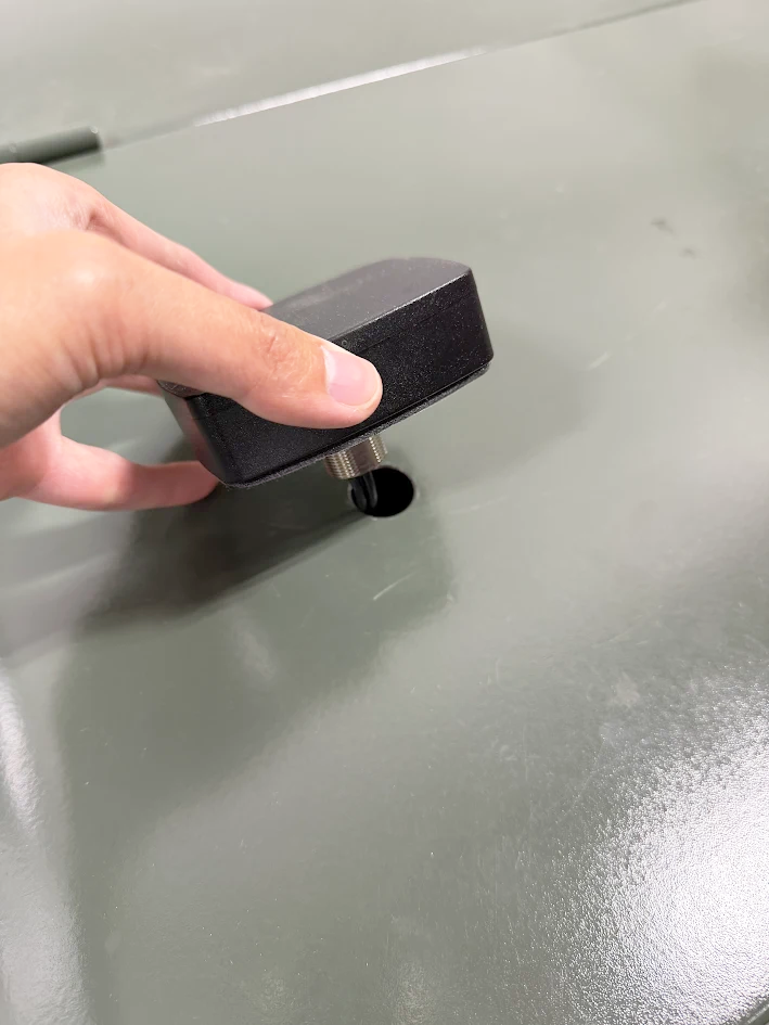
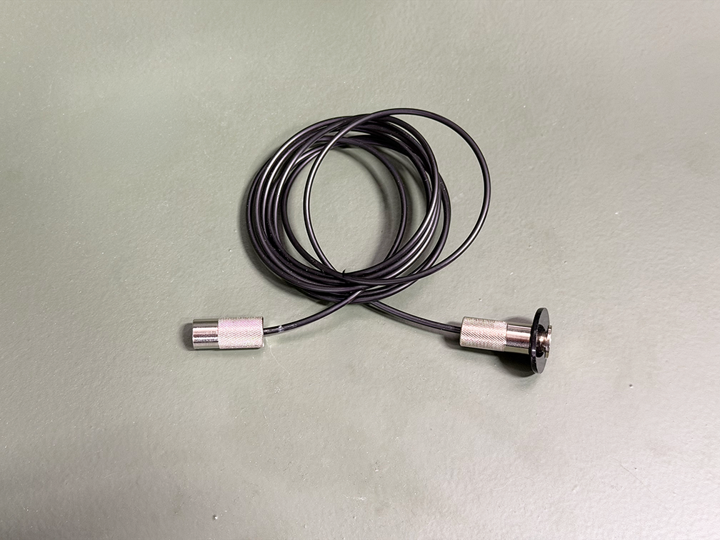
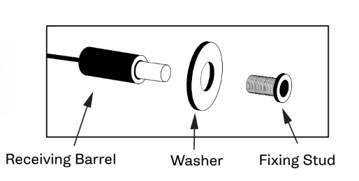
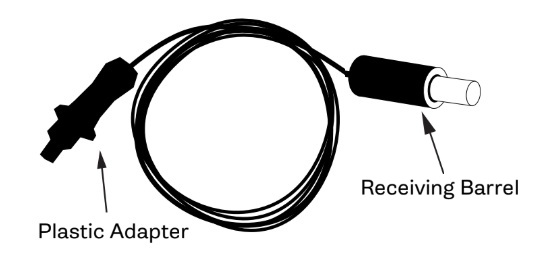
Once the Fixing Stud is unscrewed from Receiving Barrel, insert it through the drilled hole and screw the Fixing Stud into the Receiving Barrel until it firmly grips the transformer or switchgear casing.
Doc #MAY12_2026HN
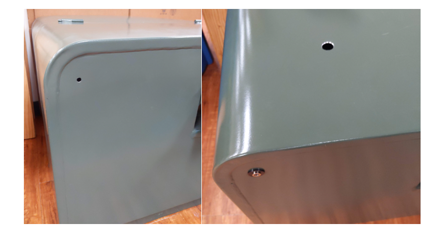
These instructions are intended to provide general guidance for installation. Depending on the application, minor cutting or modification of the enclosure may be required.
Please note that SGS cannot be responsible for any damage, warranty implications, or other outcomes resulting from such modifications. Installation decisions should be made based on the specific requirements of your application.
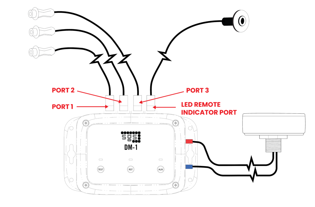
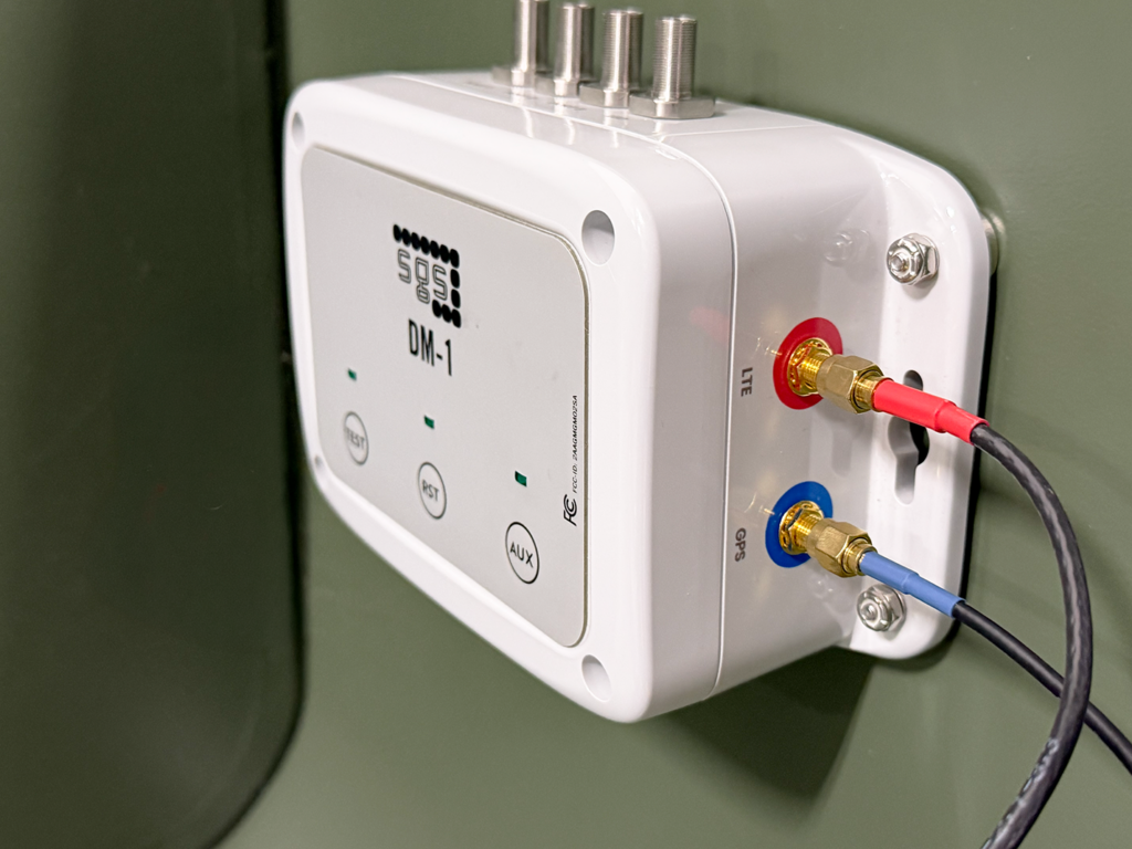
It is recommended to use SGS’s FI-3C T1 or T2 cable trainers to secure antenna cables and fiber optic cables away from elbows or other workspaces inside the cabinet.
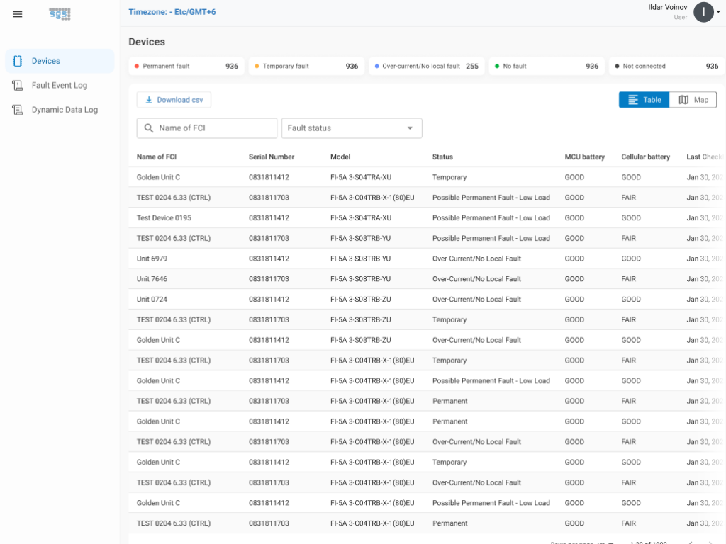
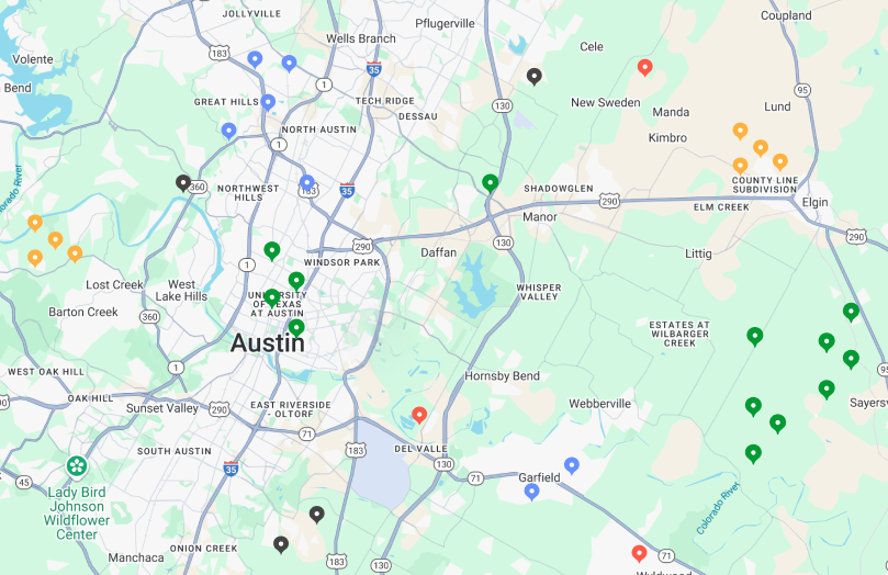
The Devices screen displays all devices associated with the user’s account, including key details such as battery status, check-in time, and location. Users can search, filter, and select a device to view daily logs, events, and average load data. Admins can edit devices to update the name, location, and Group(s) to which the device is associated.
To switch to a geographic view, select the map icon in the top right corner. To display a device on the portal map, edit the device and enter the desired latitude and longitude coordinates.
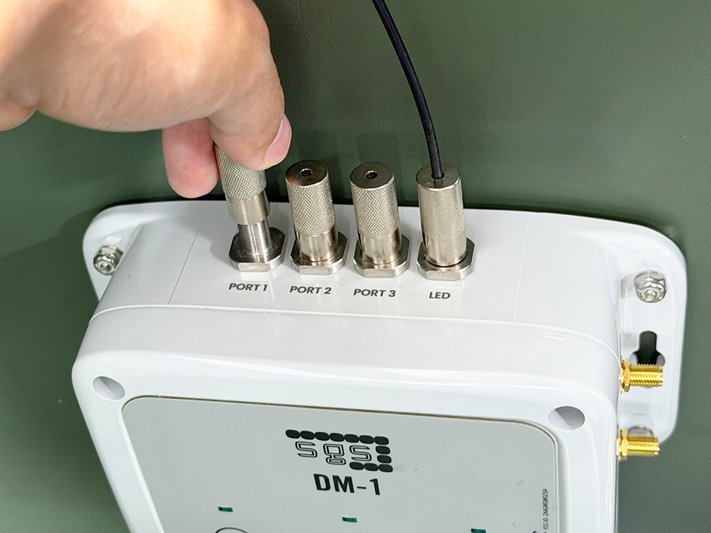
New devices are shipped in Shelf Mode to preserve battery life during storage and shipping. Refer to the product instructions for steps to disable Shelf Mode. Once disabled, confirm the device is checking in properly to ensure it is operational.
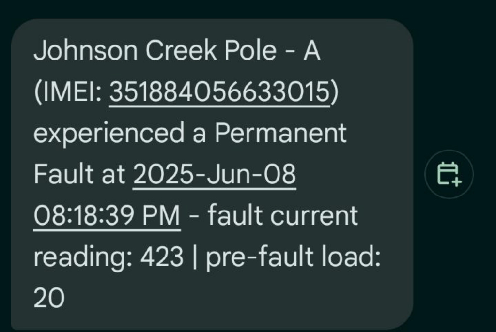
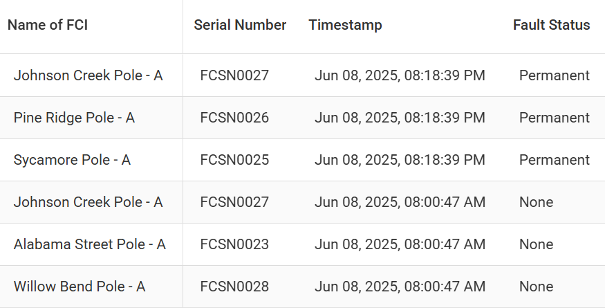
Fault Event Log displays a log of the critical events, e.g. fault events.
Dynamic Data Log displays all data registered on the portal; data may be limited to 30 days based on your user settings. These sets of data include daily check-ins as well as fault events.
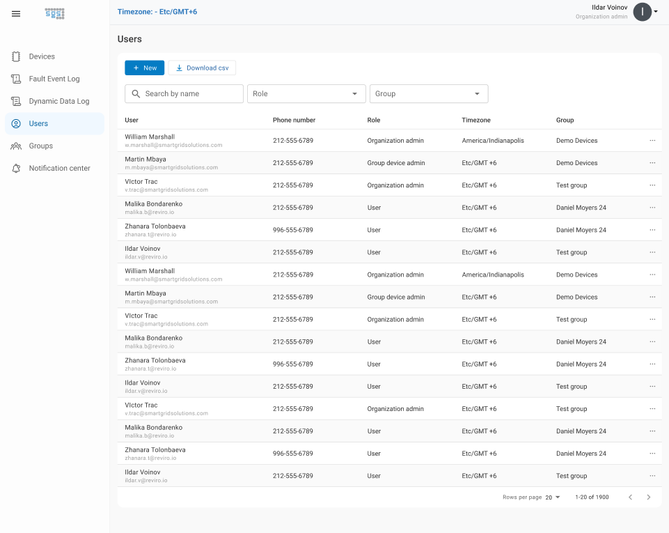
The Users screen displays all users within the organization, along with their contact details, assigned roles, and access levels. Admins can add, edit, or remove users as needed.
The Groups screen allows Admins to create and manage device Groups.
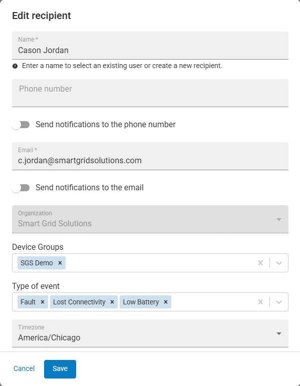
The Notification Center allows Admins to configure alerts by defining which events trigger notifications and which Recipients receive them.
Recipients can be email addresses or phone numbers and are not required to be Users of the portal.
Admins can configure:
Notifications are sent for events related to devices within assigned Groups.